


Key Model Framework
3. Innovative & Technology Initiatives
2.1 O&M Input on Design for New Building
Design for Maintainability emphasises the importance of timely integration of design and construction knowledge with O&M experience into the project design in order to optimise building life.
Maintainability should be considered, and incorporated into the building system design, ensuring the ease, accuracy, safety, and economy of maintenance tasks within that system. Maintainability refers to the effectiveness and efficiency of maintenance activities. New working practices encouraged, such as Building Information Modelling for Asset Management (BIM-AM), require the involvement of asset owners and FMs to understand the information they require on handover. FMs should be involved during design stage and ensure the information handed over by the contractor fits their specific needs.
2.1.1 General Practice
2.1.2 Good Practice

2.1.3 Best Practice
2.2 Asset Information (Documentation)
Asset Information should be compiled, covering all major items of Electrical Installations in a format that is useful to the FM and Maintenance Service Provider. The information should be placed in readily accessible locations, and updated regularly with:
2.2.1 General Practice
2.2.2 Good Practice
2.2.3 Best Practice

2.3 Operation Procedures
Operational efficiency refers to the lifecycle, cost-effective mix of preventive, predictive, and reliability-centred maintenance technologies, coupled with equipment calibration, tracking, and computerised maintenance management capabilities all targeting reliability, safety, occupant comfort, and system efficiency
2.3.1 General Practice

2.3.2 Good Practice
2.3.3 Best Practice
2.4 Emergency Preparedness
Building Emergency Preparedness is an effort to connect the emergency planning and response with the building users. The goal is to train personnel in basic emergency response actions, who know the building and occupants and can act as a resource and liaison to the stakeholders and building users.
An emergency action plan should identify all the potential hazards associated with the Electrical Installations, with a personnel responsibility matrix for allocating appropriate resources. The written plan should become an action document, updated according to an appropriate timeframe to ensure accurate information, such as updated contact information is provided.
2.4.1 General Practice
2.4.2 Good Practice
2.4.3 Best Practice
2.5 Preventive Maintenance Procedures / Standards
The goal of Preventive Maintenance is to prevent equipment failure caused by fatigue, neglect, or normal wear, through replacing worn components before actual failure. Planned Maintenance and Condition Based Maintenance activities include partial or complete overhauls at specified periods, and include oil changes, lubrication, minor adjustments, and so on. Typical procedures recommend that personnel record equipment deterioration upon any inspection to facilitate the replacement or repair of worn parts before any system failure.
The Preventive Maintenance Program must include the methodology and record for all actions that are necessary to maintain the optimal functioning of the Electrical Installations. The required maintenance procedures will be unique to each property and the systems within these facilities.
2.5.1 General Practice
2.5.2 Good Practice
2.5.3 Best Practice

2.6 Corrective Maintenance
The goal of every maintenance team is to be fast and effective, especially when it comes to unexpected breakdowns of critical plant and equipment, aiming to achieve:
2.6.1 General Practice
2.6.2 Good Practice

2.6.3 Best Practice
2.7 Maintenance Record Management
Good management of maintenance records is essential for ensuring that a piece of equipment is performing in line with the design specification and intent, and can help to determine its preventive maintenance schedule. It also assists service technicians with diagnosing repeated problems with a plant or equipment. Clear records can also provide assistance in legal proceedings, if ever necessary.
2.7.1 General Practice
2.7.2 Good Practice
2.7.3 Best Practice
2.8 Spare Parts Management
Spare parts management refers to a systematic and structured way to store and extract spare parts efficiently for any maintenance activity. A good system should minimise downtime during service disruption and simplify equipment maintenance.
2.8.1 General Practice
2.8.2 Good Practice
2.8.3 Best Practice
2.9 Addition, Alteration and Replacement (Planning and Implementation)
This includes the analysis, procurement, and management on additions, alterations as well as disposal and replacement of electrical Installations to meet the organisational long-term objectives.
2.9.1 General Practice
2.9.2 Good Practice

2.9.3 Best Practice
2.10 Incident Management
Incident management refers to the "the combination of facilities, equipment, personnel, procedures and communications operating within a common organisational structure, designed to aid in the management of resources during incidents".
When a service is disrupted or fails to deliver the promised performance during service hours, it is essential to restore the service to normal operation as quickly as possible. In addition, any condition that has the potential to result in a breach or degradation of service ought to trigger a response that prevents the actual disruption from occurring. These are the objectives of incident management.
2.10.1 General Practice
2.10.2 Good Practice
2.10.3 Best Practice
2.11 Environmental and Safety Management
Environmental and Safety Management ensures that operations are safe for all building users and
visitors. Building Owners are obliged to implement all reasonable precautions to protect the environment, and maximise the building's life cycle efficiencies.
2.11.1 General Practice

2.11.2 Good Practice

2.11.3 Best Practice
2.12 Application of Technologies
Technologies and tools can be used to lower the cost of implementing and managing O&M best management practices.
2.12.1 General Practice

2.12.2 Good Practice
2.12.3 Best Practice
2.13 Stakeholder Management
Stakeholder management is a set of techniques that harnesses the positive influences and minimises the effect of the negative influences. It involves systematic identification, analysis, planning and implementation of actions designed to engage stakeholders. Stakeholders are individuals or groups with an interest in the building or facility operation because they are involved in the work or affected by the outcomes. Most buildings or facilities and portfolios will have a variety of stakeholders with different, and sometimes competing, interests. These individuals and groups can have significant influence over the eventual success or failure of the work.
2.13.1 General Practice

2.13.2 Good Practice
2.13.3 Best Practice
2.14 Information Management
During the life of the system, the O&M Phase is the longest and most expensive and the information system provides the most value to the organisation in this phase.
2.14.1 General Practice
2.14.2 Good Practice
2.14.3 Best Practice
2.15 Structure and Qualification of O&M Team
Structure is the people, positions, procedures, processes, culture, technology and related elements that the organisation comprises. It defines how all the pieces, parts and processes work together. This structure must be totally integrated with the strategy defined for the organisation to achieve its mission and goals. Structure supports strategy. If an organisation changes its strategy, it must change its structure to support the new strategy. When it doesn't, the structure acts like a bungee cord and pulls the organisation back to its old strategy.
2.15.1 General Practice
2.15.2 Good Practice

2.15.3 Best Practice
4.1 Guidance Notes and Codes of Practice
The readers may refer to the prevailing statutory requirements, websites of the Controlling Authorities and following documents for further information on the relevant specific requirements:-
5.1 Schedule of Test Results for Electrical Wiring (Sample)
Distribution Board Location & No.: ________________________________________
Testing Instrument: ________________________________________
| Circuit Description | Protective Device | Wining Conductor | Test Result | ||||||||||||
|---|---|---|---|---|---|---|---|---|---|---|---|---|---|---|---|
| Continuity | Insulation Resistance | Polanity | Earth Loop Impedance (Zs) (Ω) |
Functional Test | Remarks | ||||||||||
| Type | Rating (A) |
Live (mm2) |
cpc (mm2) |
Protective conductor (Ω) |
Ring fina circuit (Ω) |
L-L (MΩ) |
L-E (MΩ) |
RCD (ms) |
Other | ||||||
| Tested By: | |||||||||||||||
| Date: | |||||||||||||||
L represents live conductors, including phase conductors and neutral conductors.
| (a) Switchboards, Circuit Breakers and Main Switches | Tested by/Date (N/A if not applicable) | |
|---|---|---|
| (i) | No visible damage to impair safety. | |
| (ii) | Safe access provided. | |
| (iii) | Every circuit breaker, main switch and fuse holder(s) provided with up-to-date, legible and durable rating labels giving their ratings. | |
| (iv) | Every circuit breaker and main switch provided with a legible and durable identification label. | |
| (v) | An up-to-date schematic diagram displayed to show the main distribution system. | |
| (vi) | Link of adequate size installed in neutral circuit. | |
| (vii) | All accessible live parts screened with insulating plate or earthed metal. | |
| (viii) | The overload and fault current protection characteristics of all circuit breakers verified with secondary injection test instruments where appropriate. | |
| (ix) | Lowest insulation resistance being ___Mohms (not less than 1 Mohm) measured between phases/neutral/earth. | |
| (x) | All exposed conductive parts effectively earthed with a maximum earth fault loop impedance being ____ohms. | |
| (The following item(s) under this section shall be included for low voltage installations which was connected to supply after 1st Jun 1992) | ||
| (xi) | An up-to-date notice of periodic inspection and testing provided at point of supply (i.e. a switchboard, a circuit breaker or a distribution board) of the installation in compliance with Code 17D. | |
| (b) Substations | Tested by/Date (N/A if not applicable) | |
|---|---|---|
| (The following item(s) under this section shall be included for low voltage installations which was connected to supply after 1st Jun 1992) | ||
| (i) | A warning notice ‘DANGER SUBSTATION, UNAUTHORISED ENTRY PROHIBITED’ and ‘危險 ──── 電力分站,未經授權不得內進’ provided at every entrance of substations in compliance with Code 17A(1). | |
| (ii) | Suitable locking facilities provided for HV substations in compliance with Code 4F(1)(c). | |
| (iii) | Suitable lighting provided in compliance with Code 4F(3)(a). | |
| (iv) | Suitable ventilation provided in compliance with Code 4F(3)(a). | |
| (v) | Entrance/exit free of obstruction in compliance with Code 4F(2)(c). | |
| (c) Switchrooms | Tested by/Date (N/A if not applicable) | |
|---|---|---|
| (The following item(s) under this section shall be included for low voltage installations which was connected to supply after 1st Jun 1992) | ||
| (i) | A warning notice ‘DANGER SUBSTATION, UNAUTHORISED ENTRY PROHIBITED’ and ‘危險 ──── 有電,未經授權不得內進’ provided at every entrance of switchrooms in compliance with Code 17A(2). | |
| (ii) | Suitable locking facilities provided for HV Switchrooms in compliance with Code 4F(1)(c). | |
| (iii) | Suitable lighting provided in compliance with Code 4F(3)(a). | |
| (iv) | Suitable ventilation provided in compliance with Code 4F(3)(a). | |
| (v) | Entrance/exit free of obstruction in compliance with Code 4F(2)(c). | |
| (d) Busbar Trunking System including Rising Mains | Tested by/Date (N/A if not applicable) | |
|---|---|---|
| (i) | No visible damage to impair safety. | |
| (ii) | Phase identification marked on both ends of main cable/ conductor, and at terminations. | |
| (iii) | All joints of metal conduit or trunking to be mechanically sound, electrically continuous and protected against corrosion. | |
| (iv) | All accessible live parts screened with an insulating plate or earthed metal. | |
| (v) | Lowest insulation resistance being ______Mohms (not less than 1 Mohm) measured between phases/neutral/earth. | |
| (vi) | All metal conduit or trunking effectively earthed with a maximum earth fault loop impedance being ______ohms. | |
| (e) Meter Board/Box | Tested by/Date (N/A if not applicable) | |
|---|---|---|
| (i) | No visible damage to impair safety. | |
| (ii) | Safe access provided. | |
| (iii) | All exposed metal parts effectively earthed with a maximum earth fault loop impedance being ______ohms. | |
| (f) Overhead Lines | Tested by/Date (N/A if not applicable) | |
|---|---|---|
| (i) | No visible damage to impair safety. | |
| (ii) | A minimum height of ____metres from ground (not less than 5.8 metres for lines acrossing any place accessible to vehicular traffic, 5.2 metres in other places or not less than the tallest height restriction of ________metres). | |
| (iii) | Lowest insulation resistance being ________ Mohms (not less than 1 Mohm) measured between phases/ neutral/earth. | |
| (iv) | All metal work associated with every steel pole effectively earthed. | |
| (g) Main Cables | Tested by/Date (N/A if not applicable) | |
|---|---|---|
| (i) | No visible damage to impair safety. | |
| (ii) | Cables protected against mechanical damage. | |
| (iii) | Correct phase identification provided at both ends of the cable. | |
| (iv) | Lowest insulation resistance being ______Mohms (not less than 1 Mohm) measured between cores and cores to earth. | |
| (v) | All exposed metal parts including the cable armour effectively earthed with a maximum earth fault loop impedance being ________ohms. | |
| (h) Distribution Board | Tested by/Date (N/A if not applicable) | |
|---|---|---|
| (i) | No visible damage to impair safety. | |
| (ii) | No fuse installed in the neutral circuit. | |
| (iii) | All live parts screened with an insulating plate or earthed metal. | |
| (iv) | Phase identification provided on the distribution board. | |
| (v) | Insulation resistance of not less than 1 Mohm measured between phases/ neutral/ earth. | |
| (vi) | All exposed metal parts effectively earthed. | |
| (The following item(s) under this section shall be included for low voltage installations which was connected to supply after 1st Jun 1992) | ||
| (vii) | A warning notice ‘DANGER’ and ‘危險’ provided on the front panel of every distribution board in compliance with Code 17A(3). | |
| (viii) | A notice of periodic testing provided at or near the main distribution board incorporating a residual current device (RCD) in compliance with Code 17E. | |
| (i) Final Circuits | Tested by/Date (N/A if not applicable) | |
|---|---|---|
| (i) | No visible damage to impair safety. | |
| (ii) | All non-armoured cables susceptible to damage protected with steel conduit/trunking. Bushing and rubber grommet, where necessary, provided. | |
| (iii) | Conductor sized to suit the rating of the fuse/MCB protecting the circuit. | |
| (iv) | No cable joint in final circuit. | |
| (v) | All joints of metal conduits or trunking to be mechanically sound, electrically continuous and protected against corrosion. | |
| (vi) | For temporary installation, cables lying on the ground or attached to scaffoldings secured on suitable supports. | |
| (vii) | Insulation resistance of not less than 1 Mohm measured between phases/ neutral/earth. | |
| (viii) | All metal conduits, trunking, switch boxes and exposed metal parts effectively earthed. | |
| (ix) | Residual current devices function properly. | |
| (x) | Earth fault loop impedance and polarities of every outlet checked. | |
| (j) Motors | Tested by/Date (N/A if not applicable) | |
|---|---|---|
| (i) | No visible damage to impair safety. | |
| (ii) | Insulation resistance of not less than 1 Mohm measured between phases/ neutral/earth. | |
| (iii) | All exposed conductive parts effectively earthed. | |
| (k) Earthing | Tested by/Date (N/A if not applicable) | |
|---|---|---|
| (i) | No visible damage to impair safety. | |
| (ii) | All exposed conductive parts of the wiring installation connected to the earthing terminal with appropriate protective conductor. | |
| (iii) | Bonding/earthing connection to water pipe/ gas pipe/duct effectively connected. | |
| (The following item(s) under this section shall be included for low voltage installations which was connected to supply after 1st Jan 1985) | ||
| (iv) | A warning notice ‘SAFETY *EARTH/ ELECTRICAL CONNECT DO NOT REMOVE' and ‘安全接地終端 ──── 切勿移去’ provided at all main earthing terminal and main bonding connections. | |
| (v) | Main equipotential bonding conductors effectively connected to main water pipes, main gas pipes, other services pipes/ducting and exposed metallic parts of structural framework. | |
| (vi) | Supplementary equipotential bonding effectively provided between exposed conductive parts and extraneous conductive parts. | |
| (vii) | Exposed conductive parts of fixed equipment installed outside equipotential zone effectively earthed for the required disconnection. | |
| (viii) | Exposed conductive parts of fixed equipment installed within equipotential zone effectively earthed for the required disconnection. | |
| (ix) | Effectiveness of the main equipotential bonding connection to the main earthing terminal. | |
| (x) | Effectiveness of the main equipotential bonding connection to the lighting protection system. | |
| (l) Motors | Tested by/Date (N/A if not applicable) | |
|---|---|---|
| (i) | No visible damage to impair safety. | |
| (ii) | Insulation resistance of not less than 1 Mohm measured between phases/ neutral/earth. | |
| (iii) | All exposed conductive parts effectively earthed. | |
| (m) Neon Sign | Tested by/Date (N/A if not applicable) | |
|---|---|---|
| (i) | No visible damage to impair safety. | |
| (ii) | The fireman’s switch clearly labelled. | |
| (iii) | All high voltage equipment enclosed in an earthed metal box fitted with a ‘DANGER’ and ‘危險’ warning notice. | |
| (iv) | All live parts screened with an insulation plate or earthed metal. | |
| (v) | High voltage cables securely supported with glass or glazed porcelain. | |
| (vi) | Insulation resistance of the LV circuit being ____Mohms (not less than 1 Mohm) between phases/ neutral/earth. | |
| (vii) | All exposed metalwork permanently and effectively bonded and earthed with a maximum earth fault loop impedance of ______ohms measured at LV side. | |
*Delete whichever is inapplicable
| (a) Switchboards, Circuit Breakers and Main Switches | Tested by/Date (N/A if not applicable) | |
|---|---|---|
| (i) | Safe access and adequate clearance space provided in compliance with Code 4E. | |
| (ii) | Number of source of supply:_______ and the rating of each of them:_____ |
|
| (iii) | Maximum loading approved by the electricity supplier:_______________ | |
| (iv) | Suitable interlock scheme provided to prevent parallel operation of two or more sources of supply and 4-pole incoming and interconnecting circuit breakers provided for supply to be taken from more than one source and is interconnected in compliance with Code 6B(1)(c). | |
| (v) | Electrically and mechanically interlocked 4-pole changeover device(s) where standby generator set(s) is installed in compliance with Code 8A(1)(d). | |
| (vi) | The breaking capacity of the main switch is ________ kA and all circuit breakers/inter-connection devices are able to withstand the prospective fault current in compliance with Code 9C. | |
| (vii) | Protective relays have been correctly set and overcurrent protective devices suitably set for all circuits in compliance with Code 21A(i). | |
| (viii) | Protective type C.T. are used for protective relays. | |
| (ix) | A means of isolation provided for every circuit in compliance with Code 8A(1)(c)(i). | |
| (x) | Operation of circuit breakers and main switches checked in compliance with Code 21B(9). | |
| (xi) | Control, indication and alarm functions checked in compliance with Code 21B(2)(viii). | |
| (xii) | No undersized conductor used between the main busbar and fuse/ MCB’s in compliance with Code 13A(3). | |
| (xiii) | Fuses/MCB's matching the lowest rated conductor in the circuit in compliance with Code 9B. | |
| (xiv) | Suitable cable terminations provided in compliance with Code 25D. | |
| (xv) | Cable conductors of correct phases connected in compliance with Code 21A(b). | |
| (xvi) | Single-pole devices for protection or switching connected in phase conductors only in compliance with Code 10B. | |
| (b) Busbar Trunking System including Rising Mains | Tested by/Date (N/A if not applicable) | |
|---|---|---|
| (i) | The current rating of the rising mains is _______ amperes. | |
| (ii) | The rising mains, lateral mains and meter boards positioned at places accessible from public area. | |
| (iii) | Fire barriers provided where the busbar trunking system passes through floor slabs or walls designated as fire barriers in compliance with Code 14A(3). | |
| (iv) | Cables passing through smoke lobby protected by enclosures of adequate fire rating. | |
| (v) | Non-sheathed cables protected by conduit, trunking or ducting in compliance with Code 15. | |
| (vi) | Busbar trunking systems, cables and ductings adequately supported in compliance with Code 14A(2). | |
| (vii) | Armoured cables properly terminated to metal casing or trunking by proper cable glands in compliance with Code 25D(7). | |
| (viii) | Suitable cable lugs used for terminating cables in compliance with Code 4, Code 13C and Code 25D. | |
| (ix) | Precaution against corrosion taking on aluminium conductor joined to copper conductor in compliance with Code 25D(7)(d)(ii). | |
| (x) | Cutout fuses for tapping off supply fitted with insulated carriers in compliance with Code 26B(6)(e). | |
| (c) Overhead Lines | Tested by/Date (N/A if not applicable) | |
|---|---|---|
| (i) | A steel carrier wire provided between poles to prevent strain on conducton in compliance with Code 16A and 16H. | |
| (ii) | Substantial steel poles used to suspend cables crossing vehicular passes in compliance with Code 26K(3)(b)(ii). | |
| (iii) | Overhead cables supported on suitable insulators in compliance with Code 16B. | |
| (iv) | Suitable stay wires installed on the terminal poles and on each pole at which the line changes its direction in compliance with Code 16G(1). | |
| (v) | Minimum clearance of overhead lines to ground, roads and obstacles maintained in compliance with Code 16E(2)(a), (b) and (c). | |
| (d) Main Cables | Tested by/Date (N/A if not applicable) | |
|---|---|---|
| (i) | The cross-sectional area or each core of the main supply cable is _____mm2. Number of cables in parallel, if connected is___________. | |
| (ii) | Armoured cables properly terminated to metal casing or trunking by proper cable glands in compliance with Code 25D(7). | |
| (iii) | Cables passing through smoke lobby protected by enclosures of adequate fire rating. | |
| (iv) | Non-sheathed cables protected by conduit, trunking or ducting in compliance with Code 15. | |
| (v) | Cables and ductings adequately supported in compliance with Code 14A(2). | |
| (vi) | Cables at distribution board or busbar terminated with cable lugs in compliance with Code 4, Code 13C and Code 25D. | |
| (vii) | Main cables connected up with correct polarity | |
| (e) Distribution Board | Tested by/Date (N/A if not applicable) | |
|---|---|---|
| (i) | Safe access and adequate clearance space provided in compliance with Code 4E. | |
| (ii) | Distribution boards securely mounted on suitable supports in compliance with Code 14A(2). | |
| (iii) | A suitable switch provided to control each distribution board in compliance with Code 8A(1)(a). | |
| (iv) | Phase barriers for 3-phase distribution board provided in compliance with Code 21A(g). | |
| (v) | The breaking capacity of MCB is ________kA in compliance with Code 9. | |
| (vi) | Suitable tools for withdrawal of fuses at a fuse board provided, where necessary in compliance with Code 9E(d). | |
| (vii) | Circuits connected to MCB or fuse in accordance with the schematic diagram in compliance with Code 6A(b). | |
| (f) Final Circuits | Tested by/Date (N/A if not applicable) | |
|---|---|---|
| (i) | All fuses and single pole switches connected to the phase conductors only with correct polarity. | |
| (ii) | Wiring for emergency lightings and fire services installation segregated from other wirings in compliance with Code 5B(1)(b). | |
| (iii) | Low voltage circuits segregated from extra low voltage circuits in compliance with Code 5B(1)(a). | |
| (iv) | Cables of all phases and neutral of the circuit bunched and contained in the same conduit in compliance with Code 25A(1)(f). | |
| (v) | Exposed insulated non-sheathed cables protected in compliance with Code 15. | |
| (vi) | Wiring inside false ceiling protected by conduit/trunking or metallic sheath in compliance with Code 25C(1)(f). | |
| (vii) | Socket outlets installed below 1.5m from floor being shuttered type complying to the prescribed requirements. | |
| (viii) | No socket outlet installed close to water tap, gas tap or cooker so as to avoid danger in compliance with Code 25E(d). | |
| (ix) | Floor socket outlets protected with suitable cover in compliance with Code 25E(b). | |
| (x) | No 2-pin sockets installed. All socket outlets connected with protective conductors and live conductors terminated at correct terminals. | |
| (xi) | Radial final circuits using 5A/15A socket outlets in compliance with Code 6D. | |
| (xii) | Final circuits using 13A socket outlets in compliance with Code 6E. | |
| (xiii) | Final circuits using industrial socket outlets in compliance with Code 6F or 6G or 6H. | |
| (xiv) | Circuit protective conductor is formed by the enclosure and a separate protective conductor between the earthing terminal of socket outlet and its associated metal box provided in compliance with Code11D(3). | |
| (xv) | Circuit protective conductor is not formed by the enclosure and a separate protective conductor to the earthing terminal of socket outlet provided in compliance with Code 11D(3). | |
| (xvi) | Residual current device of 30 mA rated residual operating current provided for all socket outlets in compliance with Code 11B(b)(i). | |
| (xvii) | Means of isolation provided for every fixed appliance in compliance with Code 8A(1)(c). | |
| (xviii) | All chokes, starters and capacitors of discharge lamps enclosed in earthed metal box(es) and suitably ventilated in compliance with Code 26H(4)(c). | |
| (xix) | Phase conductors connected to the centre contact of the Edison-type screw lamp holders in compliance with Code 21B(6)(ii). | |
| (xx) | No switches other than a switch fed from a safety source or operated by an insulation cord or rod or a push-button type of switch having an insulated button of a large surface area provided in bathrooms in compliance with Code 26A(3)(d). | |
| (xxi) | Shaver supply unit complying with IEC 61558-2-5 or equivalent in compliance with Code 26A(3)(e). | |
| (xxii) | Socket outlet in bathroom installed beyond Zone 2 (i.e. 0.6m away from shower basin or bathtub) protected by an RCD with a residual operating current not exceeding 30mA or protected by an isolating transformer to IEC 61558 in compliance with Code 26A(3)(j). | |
| (xxiii) | No fixed luminaire nor fixed heater having unguarded heating elements installed within reach of a person using the bath or shower in compliance with Code 26A(3)(h). | |
| (xxiv) | All circuits supplying electrical equipment with exposed conductive parts within 2.25m height above finished floor level in bathroom protected by RCD having a rated residual operating current not exceeding 30mA in compliance with Code 26A(3)(a). | |
| (xxv) | Appliances exposed to weather being splashproof type in compliance with Code 15A. | |
| (xxvi) | Luminaires, switches, sockets and plugs, cable couplers installed outdoor, being splashproof type in compliance with Code 15A. | |
| (xxvii) | General/site lighting readily accessible to the public supplied from a safety source in compliance with Code 26K(3). | |
| (xxviii) | General/site lighting not readily accessible to the public and not supplied from a safety source, protected by RCD having a rated residual operating current not exceeding 30 mA. | |
| (g) Motors | Tested by/Date (N/A if not applicable) | |
|---|---|---|
| (i) | A local switch provided to control every motor in compliance with Code 8A(4)(a). | |
| (ii) | Means provided to prevent unexpected restarting of motors where such restarting might cause danger in compliance with Code 8A(4)(c). | |
| (iii) | Flexible conduits terminated with suitable brass bushes in compliance with Code 25A(2)(b)(i). | |
| (iv) | Separate supply to motor heaters having its terminals screened, with warning notice provided. | |
| (h) Earthing | Tested by/Date (N/A if not applicable) | |
|---|---|---|
| (i) | Rod electrode(s) having a minimum diameter 12.5mm copper or 16mm galvanised or stainless steel used in compliance with Code 12C(2)(a) and (b). | |
| (ii) | Copper tape electrode having a cross-section of not less than 25mm x 3mm in compliance with Code 12C(3)(a). | |
| (iii) | Copper plate electrode not less than 3mm in thickness and having a maximum dimension of 1 200mm x 1 200mm in compliance with Code 12C(4). | |
| (iv) | No gas/water pipe used as earth electrodes in compliance with Code 12C(1)(b). | |
| (v) | A test link provided at the main earthing terminal. | |
| (vi) | Minimum size of protective conductor used in compliance with Table 11(1). | |
| (vii) | Protective conductor up to and including 6mm2 with green and yellow insulation sheath used throughout its length. | |
| (viii) | Bonding conductors of ________mm2 (not less than 150mm2 copper equivalent) used for connection to the earthing terminal of the electricity supplier’s transformer(s) in compliance with Code 11G(b). | |
| (ix) | Bonding conductors of ________mm2 (not less than 150mm2 copper equivalent) used for connection to the exposed conductive parts of the electricity supplier’s underground cable(s) in compliance with Code 11G(b). | |
| (x) | Copper links provided at joints of metallic trunking which forms part of a protective conductor in compliance with Code 14A. | |
| (xi) | Separate protective conductors provided for all flexible conduits in compliance with Code 11D(3)(b). | |
| (i) Lightning Protection | Tested by/Date (N/A if not applicable) | |
|---|---|---|
| (i) | Air termination network/down conductor/earth termination network having good continuity in compliance with relevant standard listed under Code 26I. | |
| (ii) | Joints and connections are mechanically and electrically sound in compliance with relevant standard listed under Code 26I. | |
| (iii) | Connection link to the main earthing terminal provided in compliance with relevant standard listed under Code 26I. | |
| (iv) | Test joint provided in compliance with relevant standard listed under Code 26I. | |
| (v) | Rod electrode(s) having a minimum diameter 12.5mm copper or 16mm galvanised or stainless steel used in compliance with Code 12C(2)(a) and (b). | |
| (vi) | Copper tape electrode having a cross-section of not less than 25mm x 3mm in compliance with Code 12C(3)(a). | |
| (vii) | Copper plate electrode not less than 3mm in thickness and having a maximum dimension of 1 200mm x 1 200mm in compliance with Code 12C(4). | |
| (viii) | No gas/water pipe used as earth electrodes in compliance with Code 12C(1)(b). | |
| (ix) | Measured earth termination network resistance to earth not more than 10 Ohm when the connection to main earthing terminal disconnected in compliance with relevant standard listed under Code 26I. | |
| (x) | No evidence of corrosion likely to lead deterioration of the lightning protection system. | |
| (j) High Voltage Discharge Lighting (Neon Signs) | Tested by/Date (N/A if not applicable) | |
|---|---|---|
| (i) | __________ ampere control switch fitted with a removable handle or locking facilities in compliance with Code 26H(2)(b). | |
| (ii) | Fireman's switch provided with the ‘OFF’ position at the top in compliance with Code 8B(4)(g)(ii). | |
| (iii) | High voltage cables exceeding 1 metre in length for connection between lamps and transformers, being metal sheathed or armoured. | |
| (iv) | Bare or lightly insulated conductors for high voltage connection protected with glass tubing. | |
| (k) Warning Notices and Labels | Tested by/Date (N/A if not applicable) | |
|---|---|---|
| (i) | Warning notices for substations and switchrooms provided in compliance with Code 17. | |
| (ii) | Warning notices for earthing and main bonding connections provided in compliance with Code 17. | |
| (iii) | All switchgears, distribution boards and electrical equipment properly labelled in compliance with Code 4D(1). | |
| (l) Installation Having Both New and Old Cable Colours | Tested by/Date (N/A if not applicable) | |
|---|---|---|
| (i) | Warning notice provided in compliance with Code 17 and Appendix 18. | |
| (ii) | Proper labels provided near the cable termination interface to identify new colour cables/conductors for 1-phase circuits in compliance with Appendix 18. | |
| (iii) | Proper labels provided near the cable termination interface to identify both the new and old colour cables / conductors for 3-phase circuits in compliance with Appendix 18. | |
| (iv) | Conductors are properly identified in compliance with Code 13D(2). | |
| (a) Power Generating Equipment | Tested by/Date (N/A if not applicable) | |
|---|---|---|
| (i) | The solar PV panels are certified by the recognised national/international organisations or relevant testing and certification authorities complying with relevant safety standards such as IEC 61215, BS EN 61215, IEC 61730, UL 1703 or equivalent. | |
| (ii) | Other renewable energy power generating equipment (e.g. wind turbine) complies with relevant international design/safety standards. | |
| (b) Inverter | Tested by/Date (N/A if not applicable) | |
|---|---|---|
| (i) | Anti-islanding function incorporated (with tripping time as required by the Electricity Supplier). | |
| (ii) | Synchronisation check function incorporated (to ensure that connection of the inverter to the distribution system will only take place when the inverter output and the distribution system are operating in synchronism | |
| (iii) | Automatic isolation function incorporated (to isolate the REPS from the distribution system automatically when fault occurs in the REPS) | |
| (iv) | Voltage and frequency regulator incorporated | |
| (v) | Under / Over-frequency / voltage protection function incorporated (to disconnect the inverter from the distribution system when the frequency and/or voltage of the Grid falls out of normal range) | |
| (vi) | Auto-reconnection function incorporated (to reconnect the inverter back to the distribution system when the frequency and/or voltage of the Grid resumes to normal operational range for a pre-defined period of time (with such time period to be agreed with the Electricity Supplier)). | |
| (vii) | Inverter are certified by the recognised national/international organisations or relevant testing and certification authorities complying with relevant safety standards such as IEC 62109, BS EN 62109, UL 1741 or equivalent. | |
| (c) Lightning Protection | Tested by/Date (N/A if not applicable) | |
|---|---|---|
| (i) | Proper lightning protection systems provided for the outdoor equipment. | |
| (d) Outdoor Installation | Tested by/Date (N/A if not applicable) | |
|---|---|---|
| (i) | Equipment installed outdoor being selected and erected in compliance with Code 15 of CoP. | |
| (e) REPS Circuit | Tested by/Date (N/A if not applicable) | |
|---|---|---|
| (i) | DC protection devices provided for the circuits between renewable energy power generating equipment and inverter in compliance with Code 9 of CoP. | |
| (ii) | Inverter incorporated with isolation transformer or separated isolation transformer in compliance with IEC 61558 or equivalent provided. | |
| (iii) | Pre- & post-meter lockable switches (DP / 4P) provided for isolating all sources of supply from the Grid and REPS to Renewable Energy Meter. | |
| (iv) | The earth fault loop impedance of the circuit in compliance with Code 11 of CoP. | |
| (v) | Operation of isolators, circuit breakers and switches checked in compliance with Code 21B(9) of CoP. | |
| (vi) | The RCD/RCBO trip time checked in compliance with Code 21B(9) of CoP (if applicable). | |
| (f) Earthing | Tested by/Date (N/A if not applicable) | |
|---|---|---|
| Appropriate protective conductors effectively connected. | ||
| (g) Notice and Labels | Tested by/Date (N/A if not applicable) | |
|---|---|---|
| (i) | Notice displayed at the facility showing the name and registration number of the REC employed for maintaining the generating facility in continuous safe work order checked in compliance with Code 17 of CoP. | |
| (ii) | Dual power supply warning labels displayed at all electrical equipment with dual power supply sources checked in compliance with Code 17 of CoP. | |
| (iii) | DC warning labels displayed at DC switchgear checked in compliance with Code 17 of CoP. | |
| (a) Switchboard, Circuit Breakers | Tested by/Date (N/A if not applicable) | |
|---|---|---|
| (i) | No visible damage to impair safety in compliance with Code 21A. | |
| (ii) | Safe access and adequate clearance space provided in compliance with Code 4E. | |
| (iii) | Work done properly recorded in log book in compliance with Code 4H(2) (d). | |
| (iv) | Every circuit breaker provided with a legible and durable identification label in compliance with Code 4D(1). | |
| (v) | An up-to-date schematic diagram displayed in compliance with Code 6A(b). | |
| (vi) | All accessible live parts screened with insulating plate or earthed metal in compliance with Code 4C(2)(b). | |
| (vii) | All exposed conductive parts effectively earthed in compliance with Code 11D. | |
| (viii) | Earthing system effectively connected in compliance with Code 12. | |
| (ix) | Warning notice displayed at main bonding connections in compliance with Code 17B. | |
| (x) | All protective devices are functioned properly and correctly set in compliance with Code 21B(9). | |
| (xi) | Padlock facilities for shutters provided in compliance with Code 21C(c). | |
| (xii) | Maintenance test carried out according to relevant recognised standards and manufacturers’ recommendation, where appropriate, with test reports (insulation resistance test, pressure test, ductor test, oil dielectric strength test etc.) in compliance with Code 21D(2). | |
| (b) Main Cables | Tested by/Date (N/A if not applicable) | |
|---|---|---|
| (i) | No visible damage to impair safety in compliance with Code 21A. | |
| (ii) | Cables protected against mechanical damage and suitably supported in compliance with Code 25C. | |
| (iii) | All exposed metal parts including the armour effectively earthed in compliance with Code 11D. | |
| (iv) | Maintenance test carried out according to relevant recognised standards and manufacturers’ recommendation, where appropriate, with test reports (insulation resistance test, pressure test etc.) in compliance with Code 21D(2). | |
| (c) Transformers/Motors | Tested by/Date (N/A if not applicable) | |
|---|---|---|
| (i) | No visible damage to impair safety in compliance with Code 21A. | |
| (ii) | All accessible live parts screened with insulating plate or earthed metal in compliance with Code 4C(2)(b). | |
| (iii) | Proper ventilation provided to avoid excessive temperature rise in compliance with Code 4F(3). | |
| (iv) | Maintenance test carried out according to relevant recognised standards and manufacturers’ recommendation, where appropriate, with test reports (insulation resistance test, pressure test, oil dielectric strength test etc.) in compliance with Code 21D(2). | |
| (d) Earth | Tested by/Date (N/A if not applicable) | |
|---|---|---|
| (i) | A warning notice ‘SAFETY EARTH CONNECTION—DO NOT REMOVE’ and ‘ 安全接地終端──切勿移去 ’ provided at all main earthing terminal and main bonding connections in compliance with Code 17B. | |
| (ii) | Earthing conductors of adequate size. | |
| (e) DC Battery System | Tested by/Date (N/A if not applicable) | |
|---|---|---|
| (i) | Condition of battery system. | |
| (ii) | Voltage of each battery cell measured. | |
| (f) Operation and Testing Tools and Equipment | Tested by/Date (N/A if not applicable) | |
|---|---|---|
| (i) | Proper operation tools and equipment provided for switching and isolation use. | |
| (ii) | Suitable self-test high voltage tester provided for verifying equipment dead. | |

1.1 About This Best Practice Booklet

1.2 Target Audience
While in daily operations, the safety, system reliability, operational efficiency and sustainability of the assets rely on the daily operation and maintenance practices. In this regard, some information and recommendations to the interest of the trade stakeholders are outline in this Booklet as reference.

1.3 How to Use This Best Practice Booklet
• Operation and Maintenance and
• Alteration, Addition and Replacement.
The 15 key attributes are the key main considerations for achieving good or best performance in asset management of the electrical Installations in buildings. Three levels of guiding principles, namely general, good and best practices, with associated examples of trade practices have been defined in each key attribute as reference. An additional chapter on “Innovative and Technology Initiatives” has also been included about the trend of technologies likely to be adopted to upraise the operation and maintenance service.
| Level | Category | Description |
|---|---|---|
| Level 1 | General Practice | Involving general operating practices in fulfilling statutory requirements and aligning common practice in the trade industry |
| Level 2 | Good Practice | Involving good operating practices with higher standard on enhancing either asset safety, system reliability, operational efficiency or sustainability |
| Level 3 | Best Practice | Involving best operating practices with highest standard on asset management with use of innovative technologies or relevant life-cycle considerations |
The figure provides an illustrative map for the 15 key attributes in different sections of the booklet.
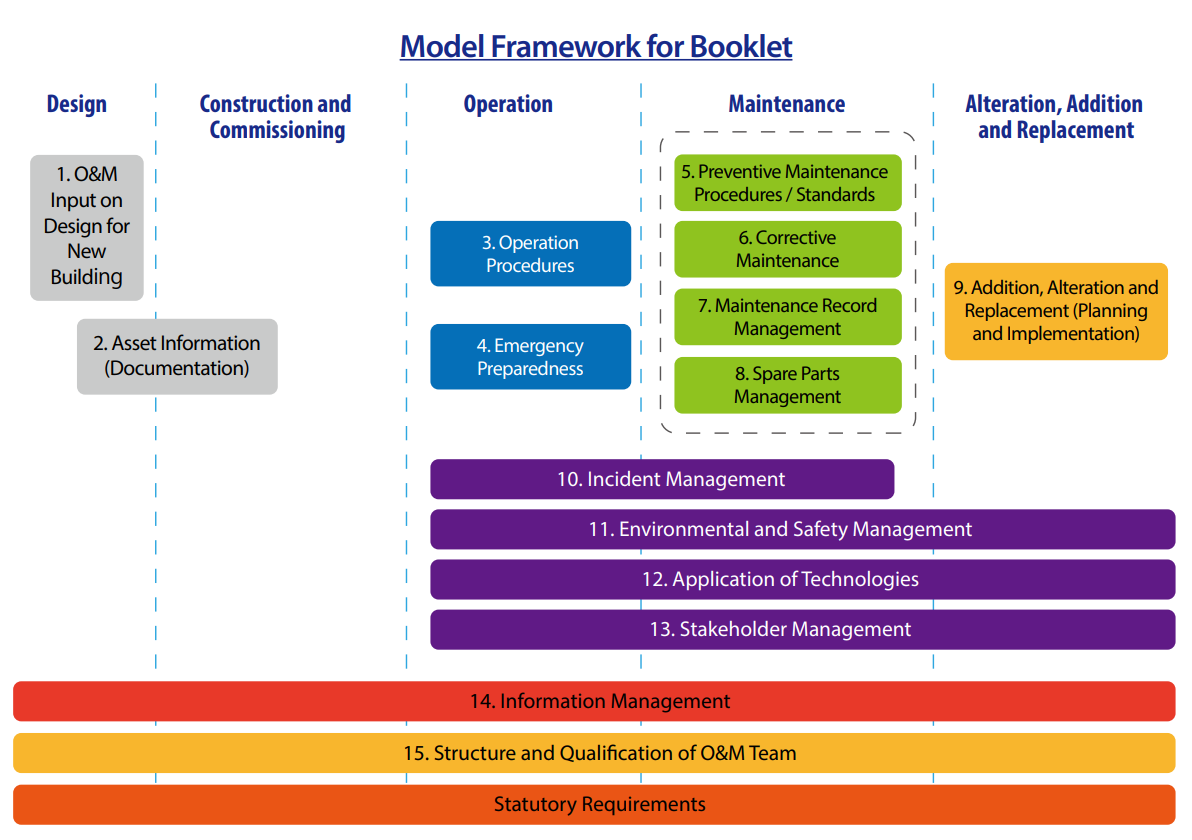
A summary of the contents in this booklet is as follows:
The 15 key attributes are:
- O&M Input on Design for New Building – It is important for Design Engineers to consider operability, accessibility and maintainability right from the planning and design of a facility, through its life cycle.
- Asset Information (Documentation) – Good documentation is essential for good operation and maintenance. This section describes the key documents that are required for the efficient operation and maintenance of Electrical Installations.
- Operation Procedures – All activities associated with the routine, day to day use, support, and maintenance of a building or physical asset; inclusive of normal/routine maintenance. O&M procedures at the system level do not replace manufacturers' documentation for specific pieces of equipment, but rather supplement those publications and guide their use.
- Emergency Preparedness – Being prepared for emergency is important, and emergency management allows stakeholders to anticipate the types of potential hazards that could occur, and to think of ways to reduce the impact.
- Preventative Maintenance Procedures / Standards – Preventive Maintenance (PM) consists of a series of time-based maintenance requirements that provide a basis for planning, scheduling, and executing scheduled maintenance. It is of a planned nature (versus the unplanned nature of Corrective Maintenance (CM)).
- Corrective Maintenance – This is an essential maintenance task performed to correct failures, breakdowns, malfunctions, anomalies or damages detected during inspections, or through monitoring, alarming, or reporting or any other source. The actions taken will aim to restore plant and equipment back into regular and required operation mode.
- Maintenance Record Management – This is a key part requiring efficient storage and management. Proper maintenance records minimise the number of expensive repairs, increase safeness in operation and enhance the visibility of equipment health.
- Spare Parts Management – Managing spare parts in an optimal way is an inherent and substantial part of O&M aimed at ensuring that spare parts are available in a timely manner for corrective maintenance in order to minimise the downtime of a system or equipment.
- Addition, Alteration and Replacement (Planning and Implementation) – This includes the analysis, procurement, management on additional, alteration as well as disposal and replacement of assets to meet the organisation’s long term aims and objectives.
- Incident Management – This is the essential process to restore normal service operation as quickly as possible and limit the potential disruption caused by an incident.
- Environmental and Safety Management – The Building Owner has the ultimate legal and moral responsibility to ensure the health and safety of people in and around the building and for the protection of the environment around it.
- Application of Technologies – Integration and adaptation of new technologies with innovative methods to optimise system performance as well as operational effectiveness.
- Stakeholder Management – This is a critical component to the successful delivery of any service. It allows the correlation of stakeholders with potential known triggers, such as disruptions to their normal patterns and update on work progress, etc. It also estimates the impact that these reactions may have on your project or strategies and identify whether targeted communication, mitigation or an alternative solution is required.
- Information Management – This concerns a cycle of organisational activity: involving the acquisition of information from one or more sources, and the custodianship and distribution of that information to those who need it.
- Structure and Qualification of O&M Team – It is of critical importance that all O&M teams have a proper structure and their personnel have the relevant qualifications to perform the works in a safe, responsible and accountable manner.

1.4 Stakeholder Responsibilities
It is essential that all involved stakeholders shall work collaboratively as a team. While those involved for improving the current practices, they shall commit to facilitate and provide sharing on the necessary training, practical experience, knowhow and awareness of modern technology and the skills of optimising performance in their organisations.
1.4.1 Building Owner
The Building Owner should motivate and empower all Stakeholders to deliver efficiencies through O&M practices. The policies and strategies set by the Building Owner should drive the process for setting up the implementation of maintenance contracts and efficiency measures.
1.4.2 Building Occupants (Tenants)
Tenants should adhere to the lease conditions when available, including Green Leases and Tenancy Fit-Out Guidelines, that express mutual expectations between Building Owners and Tenants with regards to operation, maintenance and performance requirements of buildings.
1.4.3 Facilities Manager
It is important for the FM to develop a maintenance regime that is geared towards delivering good outcomes in partnership with Maintenance Service Providers, who would benefit from the enhanced system efficiency. Forming good relationships and ensuring effective channels of communication including good documentation, is an important aspect to the process.
The operation and maintenance of buildings have already been facing several critical challenges, including the aging workforce, aging assets and climate change. The new generation of smart technologies such as artificial intelligence, asset management Internet of Things, building management system, building information system or even specialised drone-enabled automation applications would have brought further challenges to us with safety and well-being of occupants and visitors inside buildings elevated to a completely new level. Building O&M practitioners shall endeavour to adopt innovations, technologies and best practices/guidelines to improve the management of E&M assets, thereby enhancing the resilience and intelligence of government buildings.
Below are 3 emerging technology trends that may have impact on facilities management industry.
3.1 Technology Trend 1: Building Information Modeling for Asset Management (BIM-AM)
Although not a new technology, Building Information Modeling-Asset Management (BIM-AM) (BIM) is a tool used by contractors and architects to develop and scale virtual models of building projects. Giving building owners and operators a complete visual model of the facility prior to construction, it provides valuable insights into project delivery timelines and budgets. BIM software can help to simulate best O&M activities to testify operability and maintainability before construction.
When integrated with existing work order programs or facility maintenance software, BIM delivers on improved floor plans, asset information and financial estimates. As the technology continues to evolve, the importance of BIM in facilities management will continue to grow.
In recent years, EMSD has issued the BIM for Asset Management (BIM-AM) Standards and Guidelines for assets that need maintenance services. As far as the electrical trade is concerned, LV Switchboard, Emergency Generator, Lighting and Electrical Distribution are included. This standard provides the BIM modelling standard, coding standard and the information requirement for different types of Electrical & Mechanical (E&M) systems from construction stage to handover for building operation.
During design and construction stage, BIM is used as design visualisation and coordination tools. Meanwhile, asset information should be gradually built up in the BIM model so that by the end of the construction stage, the BIM model becomes an Asset Information Model (AIM) for handover to asset management.
3.2 Technology Trend 2: Integrated Building Management System (iBMS)
Integrated Building Management System (iBMS) is a master control system that integrates the electrical, mechanical, air-conditioning and building services (EMABS) systems into a single application for easy monitoring. Through iBMS, real-time operational parameters or asset operation data can continuously be collected from digitised equipment/installations such as electrical, lighting, emergency generator, airconditioning, lift & escalator, fire services and general electronic installations. iBMS offers an automatic fault/alarm reporting system with the pre-alarm function that enables maintenance staff to take early action to prevent potential failure. It features Building Energy Management System (BEMS) applications utilising both historical and real-time asset operation data such as energy consumption, control set points, sequence control, operation schedule, environmental conditions, etc. for identifying energy management opportunities so as to formulate control strategies and control settings to optimise the energy performance. There are also insight applications exploring the available data, such as hours of operation, cycles for a specific asset, operation conditions, fault/alarm statistics and trending, failure frequency, time to failure, etc. to monitor and analyse asset health; to identify correlations and regression among the data for unveiling of equipment degradation; and to compare drivers and risk factors so as to flag up actionable insight to detect anomalies and to augment O&M effectiveness.
For electrical installations, an iBMS application typically includes the following elements:
iBMS can help to achieve certain performance targets in respect of power quality and energy management, for example, to achieve minimum 0.95 Total Power Factor (TPF), less than 4% THD for incomers at or above 2000A, and maximum current unbalance of not exceeding 10% for circuits at or above 400A.
3.3 Technology Trend 3: Predictive Maintenance using Artificial Intelligence (AI), Internet of Things (IoT) and Big Data
Artificial intelligence (AI) is the broader concept of machines being able to carry out tasks in a smart manner. AI also refers to machines imitating and bettering human performance. More adaptive than traditional systems, AI holds an array of capabilities for enhanced performance in the FM industry.
A part of AI, machine learning is a current application that provides machines access to data and allows them to draw insights on their own. With machine learning, FM organisations can better predict how much time an asset, such as a building, has before its performance degrades or fails. From online chatbots in customer service to finding patterns in historical data through the use of algorithms, AI will expand and benefit all departments within an FM organisation.
The Internet of Things (IoT) refers to the network of internet accessible devices utilised by organisations. Relying on tools such as sensors, thermostats and actuators to evaluate data and reduce the amount of energy used for tasks, IoT systems effectively reduce energy bills and provide insightful data to improve occupancy within all facilities.
With various sensors generating data, FM organisations are able to identify issues and potential problems faster and easier.
Big data refers to data analytics involving large amounts of data available from different sources or systems, such as condition monitoring systems in the FM industry. Traditionally these datasets are stored and analysed independently. With the advent of IoT and other technological advancement, the discrete datasets can now be stored and analysed together for a more complete picture of asset health or for predictive analytics.
Predictive maintenance is generally conducted based on data analysis on fault history and equipment condition. Implementation of iBMS or similar platform for digitised asset management, together with the application of AI, IoT and big data, can strengthen predictive maintenance of the assets. It can predict possible equipment failure and hence facilitating overhaul/replacement/repair before the predicted failure. As a result, advantages like better asset availability (less downtime), improved system reliability, shortened maintenance time and reduced maintenance costs can be achieved.
3.4 Technology Initiatives
Based on the above five technology trends, the technology initiatives in respect of the 15 key attributes are summarised below for reference.
| O&M Aspect | Feasible Initiatives | Reference |
|---|---|---|
| O&M Input on Design for New Building |
a)
Design and construct electrical installations with BIM;
b)
Simulate best operation and maintenance activities using BIM or other simulation
software to testify operability and maintainability of electrical installations
before construction.
|
•
BIM for Facility Managers issued by International Facility Management Association
(IFMA)
•
BIM-AM Standards and Guidelines issued by EMSD
•
Housing Authority BIM Standards and Guidelines
|
| Asset Information (Documentation) |
a)
Adopt computerised asset information model such as BIM-AM to maintain all
electrical asset information under an efficient AM system;
b)
Inspect, digitise and upkeep latest record and logbook for electrical installations
and equipment on regular basis;
c)
Implement mobile solution for AM record retrieval and updating, e.g. O&M manual,
fault history, etc.;
d)
Adopt Radio Frequency Identification (RFID) or QR code for AM.
|
•
BIM for Facility Managers issued by IFMA
•
BIM-AM Standards and Guidelines issued by EMSD
•
Construction Industry Council BIM Standards
|
| Operation Procedures |
a)
Simulate operation procedures with BIM;
b)
Adopt cloud-based technology to store information of electrical installations and
equipment to be accessed by O&M personnel when needed;
c)
Implement IoT-enabled self-diagnosis function for the healthiness of major
electrical equipment;
d)
Incorporate on-line condition monitoring and mobile technologies on electrical
systems to improve maintenance and reduce downtime.
|
|
| Emergency Preparedness |
a)
Identify affected areas by the electrical incidents using BIM to facilitate
effective execution of the emergency plan.
|
|
| Preventive Maintenance Procedure / Standards |
a)
Adopt new technology and innovative system for conducting of electrical healthy
check;
b)
Adopt IoT, AI and Big data for carrying predictive maintenance to eliminate
electrical breakdown.
|
|
| Corrective Maintenance |
a)
Adopt creative method and methodology for improvement of fault report, fault
attendance and progress reporting.
|
|
| Maintenance Record Management |
a)
Adopt computerised monitoring system to maintain detailed digitised maintenance
information with capability for prompt alert, review and further analysis by AI, big
data analytic, etc.
|
|
| Spare Parts Management |
a)
Utilise an automatic inventory control system to manage spare parts inventory by
prediction of spare parts requirement using AI for advance and on-time spare parts
procurement.
|
|
| Incident Management |
a)
Consider advanced management tools to help optimise system performance, e.g., BIM –
asset registers, equipment life-cycle track, system configuration, critical device
status, maintenance history, installation visualisation, etc.;
b)
Adopt IoT technologies to allow quicker and instant reporting and collect
maintenance data for future improvement.
|
|
| Addition, Alteration and Replacement (Planning and Implementation) |
a)
Design and construct electrical installations with BIM;
b)
Adopt advanced management tools such as integrated FM tools to allow quick search
of all equipment information and records, to enhance effectiveness of overall
planning.
|
|
| Environmental and Safety Management |
a)
Adopt online platform for paperless contract execution;
b)
Adopt creative method and methodology for enhancing safety during the maintenance
work of the electrical system.
|
|
| Application of Technologies |
a)
Apply new technology to improve the system reliability;
b)
Adopt I&T initiatives for enhancing the efficiency and effectiveness in the
delivery of services;
c)
Enable knowledge transfer from research to industry to interface science /
technology.
|
|
| Stakeholder Management |
a)
Establish a smart system to automatically notify stakeholders on the coming
schedules and progress of all O&M activities, addition, alteration and replacement
works.
|
|
| Information Management |
a)
Establish an iBMS;
b)
Create centralised database for automatic replacement planning for equipment;
c)
Establish an online real time server for storing maintenance related information
through mobile device;
d)
Provide online access of all information by maintenance party during preventive
maintenance works.
|
|
| Structure and Qualification of O&M Team |
a)
Provide training to O&M personnel so as to keep abreast with the technology
advancements.
|
4.2 International Standards
The readers may refer to the prevailing international standards as accepted by the Controlling Authorities or the approval standards for existing buildings:-


")


Last revision date: 6 Jun, 2023 This site is best viewed with: Chrome or Firefox © 2023 emsd.gov.hk