
1. Introduction
2. Design Considerations
2.1
General
2.2
PV Modules
2.3
Inverters
2.4
Power Optimisers
2.5
Surge Arresters
2.6
DC Isolating Switches
2.7
Isolation Transformers
2.8
Batteries (for Standalone or Hybrid PV Systems)
2.9
Battery Charge Controllers (for Standalone or Hybrid PV Systems)
2.10
Installation of PV Systems
2.11
Application of Technology
2.12
Others
3. Operation and Maintenance
4. Record/Documentation
5. Appendix A:Sample Checklist for Inspection and Testing of Solar PV Systems
Introduction
Installation Address: ________________________________________
| (a) PV Modules | Tested by/Date (N/A if not applicable) | |
|---|---|---|
| (i) | Check for warning signs and labels and replace if necessary. | |
| (ii) | Clean the PV modules with water to remove dust, debris and other contaminants on the module surface. | |
| (iii) | Check PV modules, junction boxes, cables and connectors for damage, such as burn marks, bubble formation, cracking, broken glass, discoloration, corrosion, etc. | |
| (iv) | Check PV modules for any loose cable connections. | |
| (v) | Use infrared camera to inspect PV modules for hot spots. | |
| (vi) | Check the functioning of the bypass diodes. | |
| (vii) | Check bonding conductor conditions. | |
| (viii) | Carry out continuity test for protective conductors and/ or equipotential bondings. | |
| (ix) | Check solar irradiance and the power output from the PV module and compare the readings with calculated power output to verify the PV module performance and identify any defective modules. | |
| (b) Supporting Frames and Structures | Tested by/Date (N/A if not applicable) | |
|---|---|---|
| (i) | Check integrity of the penetration, physical connections and fixing components to make sure each PV module is securely fixed. | |
| (ii) | Check all hardware for signs of corrosion, remove rust; re-paint and replace if necessary. | |
| (iii) | Check bonding conductor conditions. | |
| (iv) | Continuity test for protective conductors and/or equipotential bondings. | |
| (c) PV Arrays | Tested by/Date (N/A if not applicable) | |
|---|---|---|
| (i) | Check for abnormal position and movement of PV arrays. | |
| (ii) | Check open-circuit voltage, operating current of a series of strings to ensure PV modules are working properly. | |
| (d) DC Side of System | Tested by/Date (N/A if not applicable) | |
|---|---|---|
| (i) | Check for warning signs and labels and replace if necessary. | |
| (ii) | Check cable for signs of cracks, defects, pulling out of connections, loose connections, overheating, arcing, short or open circuits, and earth faults. | |
| (iii) | Check position of disconnect switches and circuit breakers and fuse status. | |
| (iv) | Check surge arrester conditions and replace as per manufacturer’s recommendations. | |
| (v) | Check for corrosion, intrusion of water or insects in the combiner box. | |
| (vi) | Carry out DC circuit tests including insulation test, polarity test, and operation of protection devices or as specified in CoP. | |
| (e) Inverters | Tested by/Date (N/A if not applicable) | |
|---|---|---|
| (i) | Check for warning signs and labels and replace if necessary. | |
| (ii) | Check ventilation conditions and clean the dust of inverter cabinet. | |
| (iii) | Check for loose cable connections. | |
| (iv) | Check for abnormal operation temperature. | |
| (v) | Check functionality such as automatic disconnection upon loss of grid power supply. | |
| (vi) | Measure the input and output power to ensure the inverters are working properly. | |
| (f) AC Side of System | Tested by/Date (N/A if not applicable) | |
|---|---|---|
| (i) | Check for warning signs and labels and replace if necessary. | |
| (ii) | Check cable for signs of cracks, defects, pulling out of connections, loose connections, overheating, arcing, short or open circuits, and earth faults. | |
| (iii) | Check for corrosion, intrusion of water or insects in the distribution board. | |
| (iv) | Check position of disconnect switches and circuit breakers and fuse status. | |
| (v) | Check for any loose electrical connection including at RE meter. | |
| (vi) | Check surge arrester conditions and replace as per manufacturer’s recommendations. | |
| (vii) | Carry out AC circuit tests including insulation test, polarity test, operation of protection devices and tripping time of residual current device/residual circuit breaker with overcurrent protection (RCD/RCBO) or as specified in CoP | |
| (g) Isolation Transformer | Tested by/Date (N/A if not applicable) | |
|---|---|---|
| (i) | Check for warning signs and labels and replace if necessary. | |
| (ii) | Inspect the conditions of isolation transformers and clean the dust from heat rejection fin. | |
| (iii) | Check the primary and secondary voltage/current/power/frequency, carry out insulation test. | |
| (h) System Test | Tested by/Date (N/A if not applicable) | |
|---|---|---|
| (i) | Check the total harmonic current distortion (should not exceed 5%) and DC injection current. | |
| (ii) | Check the voltage and current waveforms by opening the isolation switch and check the anti-islanding time is sufficient in accordance with power company’s requirements. | |
| (i) Earthing Protection System | Tested by/Date (N/A if not applicable) | |
|---|---|---|
| (i) | Check for warning signs and labels and replace if necessary. | |
| (ii) | Check for loose earthing conductor connections. | |
| (iii) | Check continuity of the earthing conductors and the earth fault loop impedance of the PV system. | |
| (iv) | Check the insulation of the earthing cables to the live cables. | |
| (v) | Check the earth fault loop impedance. | |
| (j) Lightning Protection System | Tested by/Date (N/A if not applicable) | |
|---|---|---|
| (i) | Check for warning signs and labels and replace if necessary. | |
| (ii) | Check bonding conductor conditions for any loose bonding conductor connection. | |
| (iii) | Check continuity of the bonding conductors to lightning system. | |
| (k) Instrument | Tested by/Date (N/A if not applicable) | |
|---|---|---|
| (i) | Check the monitoring instruments (e.g., pyranometers, weather sensors) to make sure they are operational. | |
| (ii) | Calibrate and replace instruments, weather sensors, and meters. | |
| (l) System Monitoring | Tested by/Date (N/A if not applicable) | |
|---|---|---|
| (i) | Monitor the operation status, performance, alarms and alert parameters. | |
| (ii) | Check building management system for PV system, check hardware for signal interface and upgrade software as necessary. | |
| (iii) | Maintain a log of cumulative power delivery (kWh to date) and generate a chart of power against date. | |
| (iv) | Check the instant solar irradiation and the energy output from the PV system and compare the system efficiency with the design figure. | |
| (m) Battery System (for off-grid system) | Tested by/Date (N/A if not applicable) | |
|---|---|---|
| (i) | Check for warning signs and labels and replace if necessary. | |
| (ii) | Clean the container or enclosure. | |
| (iii) | Check the battery bank for chemical leakage, cracks, bulging, integrity of battery enclosure, and support structures. | |
| (iv) | Check all hardware for signs of corrosion and remove rust and re-paint if necessary. | |
| (v) | Check ventilation conditions of the battery room and remove the dust on the louvres. | |
| (vi) | Check all electrical connections on battery bank for loose electrical connections. | |
| (vii) | Test battery capacity. | |
| (viii) | Check the overcharging and over-discharging functions. | |
| (n) Others | Tested by/Date (N/A if not applicable) | |
|---|---|---|
| (i) | Check the watertightness of the roof. | |
| (ii) | Check for any vegetation growth or other shade items. | |

1.1 About This Handbook
(1)
This Handbook recommends the best system design and operational practices in principle for solar photovoltaic (PV) systems.
(2)
This Handbook covers “General Practice” and “Best Practice” associated with solar PV system installation and maintenance. “General Practice” refers to general requirements in fulfilling statutory requirements and guidelines as well as aligning common practices in the trade. Whilst “Best Practice” helps to further enhance the safety and system performance of the solar PV system installations by considering exemplary practices and innovative technologies identified at the time of preparation and revision of this Handbook.

1.2 Target Audience
(1)
The target audience of this Handbook includes PV system owners, PV system operators, PV maintenance contractors, property management managers and engineering staff.

1.3 Related Ordinances, Regulations and Guidelines
(1)
The requirements for the installation, operation and maintenance of the PV system are given in the undernoted ordinances, regulations and codes of practice, etc. Readers may refer to the following documents for further information:
a)
Electricity Ordinance (Cap. 406)
b)
Code of Practice for the Electricity (Wiring) Regulations (CoP), issued by the EMSD of the Government
c)
Technical Guidelines on Grid Connection of Renewable Energy Power Systems, issued by the EMSD of the Government
d)
Guidance Notes for Solar Photovoltaic (PV) System Installation, issued by the EMSD of the Government
e)
Electricity supply rules of the relevant power companies
f)
Technical guidelines and testing & commissioning requirements for grid connection, issued by the relevant power companies
g)
Building New Territories Exempted Houses, the Lands Department of the Government
h)
Buildings Ordinance (Cap. 123)
2.1 General
(1)
Solar Photovoltaic (PV) systems in Hong Kong can be classified into three main types as below:
a)
Standalone Systems
b)
Grid-connected PV Systems
c)
Hybrid PV systems
(2)
Most of the PV systems in Hong Kong are grid connected. Grid-connected PV systems shall meet grid connection requirements and approved by power companies before connecting to the grid. In accordance with the Electricity Ordinance (EO), the owner of a grid-connected PV system shall register it with and submit the form GF1 to the Director of Electrical and Mechanical Services (the Director) unless it forms part of an electrical installation that requires a periodic test certificate to be submitted to the Director under this Ordinance.
(3)
For technical requirements relating to grid-connected PV systems, refer to the “Technical Guidelines on Grid Connection of Renewable Energy Power Systems”.
(4)
For installation and regulatory requirements on the installation of PV systems, refer to the “Guidance Notes for Solar Photovoltaic (PV) System Installation”.
(5)
Regardless of the type of the PV system, sufficient maintenance access shall be provided for the circuit breaker panels and distribution boards, and all electrical work on the PV system shall only be carried out by an appropriate Registered Electrical Worker (REW) employed by a Registered Electrical Contractor (REC) and complying with the Code of Practice for the Electricity (Wiring) Regulations (CoP).
(6)
The major components of a PV system include PV modules, inverters, power optimisers, surge arresters, isolation transformers, batteries, battery charge controllers, performance monitoring systems, etc.
2.2 PV Modules
(1)
PV cells, which convert solar light into electricity, in the market can be classified into two main categories:
a)
Crystalline silicon (monocrystalline and polycrystalline)
b)
Thin-film (amorphous silicon, copper indium diselenide (CIS) and Cadmium-telluride cells (CdTe)
(2)
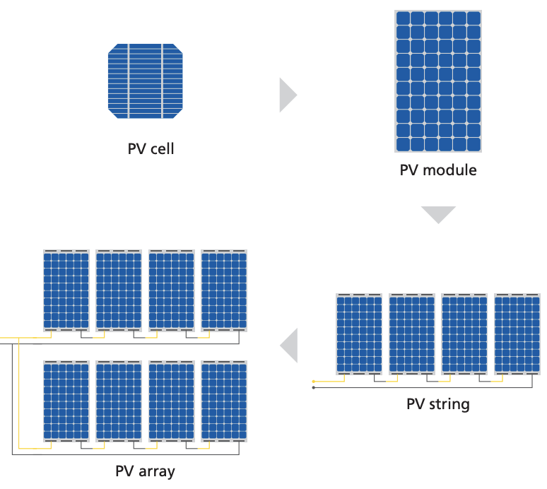
PV modules are made up from a number of PV cells. PV modules are connected in series to form a PV string while PV strings are connected in parallel to form a PV array. The performance output of the PV module is in watts per square meter, which represents the expected peak power point output of the module in watts at standard test conditions (STC).
(3)
Smart PV module is a solar module that has a power optimiser or micro-inverter embedded into the solar panel at the time of manufacturing with a view to providing easy installation, increasing power harvesting especially in the location with partial shading and providing module level monitoring. However, the capital cost will be higher than the traditional PV module.
(4)
The life expectancy of PV modules is about 20-25 years and some contractors will provide product warranty depending on procurement requirements. Before replacing the faulty PV modules, the warranty of the PV modules shall be checked.
2.3 Inverters
(1)
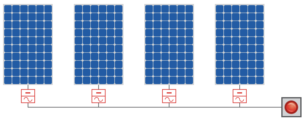
Inverters not only convert the direct current (DC) electricity generated from PV modules into alternating current (AC) electricity, but are also responsible for the intelligence of the PV system. Inverters can be classified as central inverters, string inverters and micro-inverters. Central inverters are used at system level to convert DC power generated from PV arrays to AC power. String inverters are similar to central inverters but convert DC power generated from a PV string.
(2)
String inverters provide a relatively economical option for solar PV system if all panels are receiving the same solar radiance without shading. Under shading scenarios, micro-inverters may be considered as a more efficient option than string inverters but the capital cost could be higher.
(3)
Inverters for grid connection shall produce AC electricity synchronised with the Distribution System and provide anti-islanding protection to turn off automatically in case the Grid is de-energised so as to protect the electrical workers, who may not realise that the power distribution system is still powered during the electricity supply interruption.
(4)
The life expectancy of inverters is about 10 years and some contractors will provide product warranty depending on procurement requirements. Before replacing the faulty inverter, the warranty of the inverter shall be checked.
2.4 Power Optimisers
(1)
Power optimisers are DC to DC converters and if installed at PV modules, they can maximise the electricity output of the PV system by constantly tracking the maximum power point (MPP) of each PV module individually. Power optimisers can also be installed for each PV string or PV array instead of each PV module. Similar to micro-inverters, power optimisers at module level could lessen the impact of partial shading on the overall system performance but they cost less than micro-inverters. Since power optimisers are DC to DC converters and hence inverters are always required for a grid connected system.
2.5 Surge Arresters
(1)
To protect PV systems from lightning and overvoltage risks, surge arresters should be installed at the DC side and AC side of the inverters.
2.6 DC Isolating Switches
(1)
DC isolating switches are installed at the DC side of the inverters to isolate the power supply from the PV modules. The DC isolating switches should be suitable for load-break operation to minimise the risk during the emergency switch-off of the DC supply.
2.7 Isolation Transformers
(1)
Isolation transformers are typically installed at the output side of the inverters to prevent the DC injection from the PV system into the distribution system. Excess DC injected into the distribution system would distort its voltage and cause problems to other connected system.
2.8 Batteries (for Standalone or Hybrid PV Systems)
(1)
Batteries are used for storing the electricity generated from the PV systems and supplying power to the electrical loads when the PV systems cannot meet the electricity demand. The batteries should be located in an area without extreme temperatures and with ventilation.
(2)
Batteries containing hazardous substances such as lead and sulphuric acid are classified as chemical waste and disposal of such batteries is controlled under the Waste Disposal Ordinance (Cap. 354) (WDO).
(3)
Fire services requirements on the battery rooms and electrical charging facilities shall refer to the Codes of Practice for Minimum Fire Service Installations and Equipment and Inspection, Testing and Maintenance of Installations and Equipment and associated circular letters.
2.9 Battery Charge Controllers (for Standalone or Hybrid PV Systems)
(1)
Battery charge controllers are provided in between the PV strings/arrays and the batteries. They are used to regulate the power generated from the PV modules to prevent the batteries from overcharging and/ or over discharging.
2.11 Application of Technology
2.11.1 General Practice
(1)
The performance of PV systems is dependent on solar irradiation and system conditions. PV systems are an automatic operation, but performance monitoring systems with basic output monitoring and appropriate display units are important to verify the output from the systems and whether the systems are operational.
(2)
Monitoring devices may be installed at different levels depending on system requirements and are summarised below:
| Level of Monitoring | Component/ equipment monitored | Advantages | Disadvantages |
|---|---|---|---|
| PV system level | Central inverter | Simple and relatively low installation cost | Fault at PV string/module level cannot be identified |
| Lower maintenance cost | Mismatch losses are relatively high | ||
| The electricity generated by PV system drops significantly when the inverter breaks down | |||
| PV string/ PV array level | String inverter/ string optimiser | Cost effective compared with micro-inverter/module optimiser | Fault at PV module level cannot be identified |
| Lower maintenance cost compared with micro-inverter/ module optimiser | |||
| PV module level | Micro-inverter/ module optimiser | Fault at PV module level can be identified | High installation cost |
| Mismatch losses (such as shading on one panel or different orientations of roof surfaces) can be minimised | More frequent maintenance will be required especially for large- scale systems | ||
| Maximise the power output of the PV system | |||
| Provide rapid shutdown at module level to minimise the system voltage at DC side |
Remarks:
Most market available inverters are provided with built-in MPP inputs.
2.11.2 Best Practice
Performance Monitoring System
(1)
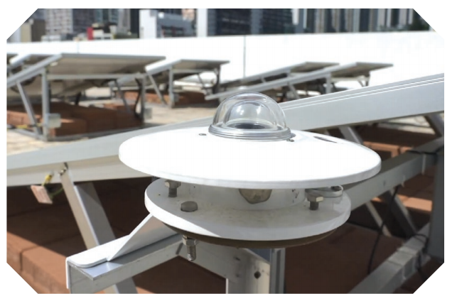
Independently calibrated microclimate stations including one or few pyranometers should be installed to record insolation data for the best practice. Recorded weather data is used to estimate how much electricity could be generated from the PV system for comparison with the actual electricity generation to check the system performance. If the system output drops to more than the one specified in the design, the operator should arrange a REC/REW to check the system components.
(2)
The performance monitoring system should remotely monitor the major components of the PV system for easy troubleshooting and effective repair. The PV system can be connected to the Building Management System (BMS) for central monitoring and supervision of the system’s performance. The real time generation data should be accessible by mobile phone apps.
Rapid Shutdown
(1)
It is recommended to adopt advanced micro-inverters or rapid shutdown devices which can assist the solar systems with module-level rapid shutdown in order to limit the voltage of a PV string and ensure a safe condition during fire or maintenance.
2.12 Others
2.12.1 General Practice
(1)
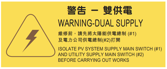
Warning notices shall be provided as required by the Electricity Ordinance (Cap. 406) and the Code of Practice for the Electricity (Wiring) Regulations (Cap. 406E). In addition, warning labels at all electrical equipment with dual power supply sources shall be provided to alert the maintenance personnel.
(2)
For inaccessible roofs, fall arrest systems such as anchoring points or protective barriers should be considered to allow safe access to the panels.
2.12.2 Best Practice
(1)
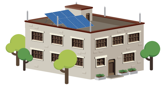
It is recommended to provide dry power type fire extinguishers for PV systems installed in private buildings or New Territories Exempted Houses, commonly known as village houses.
3.1 Factors Affecting System Performance
(1)
There are several factors that will affect PV system performance over the operational lifetime:
a)
Soiling
The build-up of dust/dirt or other contaminants on the surface of the PV modules is known as soiling. This blocks the sunlight from reaching the solar cells and reduces the electricity generated.
Soiling is significant especially in the dry season and near the construction sites. In case the PV modules are installed where cleaning cannot be carried out easily, the PV modules should be suitably tilted to allow self-cleaning.
b)
Shading
The solar path changes throughout the year, and shading effect from the parapet, trees, or other obstacles becomes severe in winter. The performance of PV modules under varying light conditions will differ significantly, which in turn will have great impact on the yield of PV systems.
The shading effect from nearby obstacles, especially from the trees or new obstacles, should be checked.

c)
Mismatch Losses
Mismatch losses are caused by differences in the characteristics of PV cells or PV modules, and the overall system performance is determined by the lowest performing panel. The typical causes of mismatch losses include non-identical electrical characteristics, shading, differences in operating temperature and replacement of new PV modules. Besides, the PV modules degrade in different ways with long term aging and this leads to an increase in mismatch losses.
A like-for-like replacement should be made as far as possible. Products from different manufacturers, cell sizes or technologies are not recommended owing to different electrical characteristics of the panels.
d)
Major Components Breakdown
Major components failure, in particular inverter failure, may cause the whole system to break down in the worst-case scenario. Bypass and blocking diodes failure will cause poor system performance. Cable damage will also cause the breakdown of the solar system. Regular checking and immediate replacement are critical.
e)
Solar Irradiance
The amount of electricity generated from a PV system depends on the amount of irradiance falling on the PV module surface. The tilt and azimuth angles of the PV module will affect the annual solar irradiation received.
The tilt and azimuth angles will be changed from time to time and should be checked regularly, especially after typhoon attacks.
3.2 Operation Procedures
3.2.1 General Practice
(1)
The system operator or the Contractor of a solar PV system should read the operation instructions recommended by the manufacturer/supplier. The owner should properly store and keep all the technical documents for future reference.
(2)
The owner should arrange regular inspections and routine maintenance and functional check of the solar PV system as stipulated in Section 3.4 below.
(3)
The owner can perform general cleaning work by using clean water and soft cloth or sponge on the PV module surface on a regular basis to maximise the electricity generation, whilst electrical work on the PV system must be carried out by a REC/REW.
(4)
For safety precautions for works on the electrical installation, refer to the CoP.
(5)
Before operating the PV system, the REC/REW should read all instructions for each product and the following procedures for electrical disconnection and restoration must be carried out prior to and after carrying out any electrical work on the PV system:
a)
Notify the owner/representative of the PV system that the system will be shut down
b)
Isolation of supply from PV system and the Grid
•
Switch OFF the lockable main switch of the PV system at the Grid supply side to isolate the supply from the Grid. Apply lock and affix appropriate warning notice(s)
•
Switch OFF the DC circuit breakers, inverters and/or associated isolation switch(es) at PV system side to isolate the supplies from PV system. Apply lock and affix appropriate warning notice(s)
•
The keys for all isolation points shall be kept by the responsible REC/REW
c)
Verification of complete de-energisation of the system
d)
After completion of work, the REC/REW shall inspect, test and certify that the installation is safe for energisation
e)
Restoration of supply from PV system and the Grid
•
Remove the warning notice(s) and unlock the isolation switch(es) at PV system side. Switch ON the DC circuit breakers, inverters and/or isolation switch(es) to restore supply from PV system
•
Remove the warning notice(s) and unlock the lockable main switch of the PV system at the Grid supply side. Switch ON the main switch to restore supply from the Grid
•
Notify the owner/representative of the PV System, the REC and other relevant parties after work completion
(6)
Proper access tools such as ladders should be provided and fall arrest systems should be used.
3.3 Emergency Preparedness
3.3.1 General Practice
(1)
An up-to-date emergency contact list shall be provided and attached at the location near the installation showing the following items:
•
Name of the contact person or company
•
Telephone number
(2)
In case of emergency, the PV system shall be shut down and isolated from the Grid. Refer to Section 3.2 above for operation procedures of isolation of PV systems and the Grid.
3.3.2 Best Practice
(1)
Emergency plan/procedures including the communication flow between the PV system owner, system operator and the maintenance contractor, should be provided on site. The emergency plan/procedures should be reviewed on a regular basis.
3.4 Preventive Maintenance
3.4.1 General Practice
(1)
To maximise the yield of a PV system in its operational period, routine preventive maintenance work is essential. All preventive maintenance work shall be read in conjunction with the maintenance manual recommended by the manufacturer.
(2)
The PV system owner or system operator shall be notified about the testing or shutdown of the system.
(3)
The electrical work for the PV system shall only be carried out by a REC/ REW who shall carry out a risk assessment before commencement of work.
(4)
All testing instruments shall be calibrated by an accredited laboratory before use.
(5)
For safety precautions for works on the electrical installation, please refer to the CoP.
3.4.2 Best Practice
(1)
The maintenance schedule and procedures shall be regularly reviewed and updated against the latest statutory requirements, international standards and maintenance history.
3.4.3 Preventive Maintenance Schedule
(1)
Preventive maintenance schedule for a PV system is recommended as below:
| Components/ equipment | Description | Action | Recommended Frequency | General Practice | Best Practice |
|---|---|---|---|---|---|
| PV Modules | Warning notice inspection | Check for warning signs and labels and replace if necessary | Annual | • | • |
| General cleaning | Clean the PV modules with water to remove dust, debris and other contaminants on the module surface | Quarterly | • | • | |
| PV module inspection | Check PV modules, junction boxes, cables and connectors for damage, such as burn marks, bubble formation, cracking, broken glass, discoloration, corrosion, etc. | Bi-annual to annual | • | • | |
| Check for any loose cable connection | • | • | |||
| Hot-spot inspection | Use infrared camera to inspect for hot spots | Annual | • | ||
| Bypass diode | Check the functioning of the bypass diodes | Annual | • | ||
| Bonding conductor inspection and testing (PV metallic frame to PV metallic frame) | Check bonding conductor conditions | For every 5 years or as required by Periodic Inspection, Testing and Certification (PITC) | • | • | |
| Continuity test for protective conductors and/ or equipotential bonding | • | • | |||
| Module performance testing | Check solar irradiance and the power output from the PV modules and compare the readings with calculated power output to verify the PV modules performance and identify any defective modules | Annual (except systems with micro-inverters or power optimisers installed for each PV module) | • | ||
| Supporting Frames and Structures | Supporting system inspection | Check integrity of the penetration, physical connections and fixing components to make sure each PV module is securely fixed | Annual (Remark 1) | • | • |
| Corrosion inspection | Check all hardware for signs of corrosion and remove rust; re-paint and replace if necessary | Annual | • | • | |
| Bonding conductor inspection and testing (PV metallic frame to supporting frames, supporting frames to earth terminal) | Check bonding conductor conditions | For every 5 years or as required by PITC | • | • | |
| Continuity test for protective conductors and/or equipotential bondings | • | • | |||
| PV Arrays | Array inspection | Check for abnormal position and movement of PV arrays | Annual (Remark 1) | • | • |
| Electrical measurement | Check open-circuit voltage, operating current of a series of strings to ensure PV modules are working properly | Annual | • | ||
| DC Side of System | Warning notice inspection | Check for warning signs and labels and replace if necessary | Annual | • | • |
| Cable inspection | Check cable for signs of cracks, defects, pulling out of connections, loose connections, overheating, arcing, short or open circuits, and earth faults | Annual | • | • | |
| DC disconnect switch/circuit breakers inspection | Check position of disconnect switches and circuit breakers and fuse status | Annual | • | • | |
| Surge arrester inspection | Check surge arrester conditions and replace as per manufacturer’s recommendations | For every 5 years or as per manufacturer's recommendation | • | • | |
| Combiner box inspection | Check for corrosion, intrusion of water or insects | Annual | • | • | |
| DC circuit test | Carry out DC circuit tests including insulation test, polarity test, and operation of protection devices or as specified in CoP | For every 5 years or as required by PITC | • | • | |
| Inverters | Warning notice inspection | Check for warning signs and labels and replace if necessary | Annual | • | • |
| Dust removal from heat rejection fins and ventilation fan if provided | Check ventilation conditions and clean the dust of inverter cabinet | Bi-annual to annual | • | • | |
| Cable wiring inspection | Check for loose cable connections | Annual | • | • | |
| Operation temperature inspection | Check for abnormal operation temperature | Bi-annual to annual | • | ||
| Functional test | Check functionality such as automatic disconnection upon loss of grid power supply | Bi-annual to annual or as per manufacturer's recommendation | • | • | |
| Measure the input and output power to ensure the inverters are working properly | Annual | • | |||
| AC Side of System | Warning notice inspection | Check for warning signs and labels and replace if necessary | Annual | • | • |
| Cable inspection | Check cable for signs of cracks, defects, pulling out of connections, loose connections, overheating, arcing, short or open circuits, and earth faults | Annual | • | • | |
| Distribution board inspection | Check for corrosion, intrusion of water or insects | Annual | • | • | |
| AC disconnect switch/circuit breakers inspection | Check position of disconnect switches and circuit breakers and fuse status | Annual | • | • | |
| Surge arrester inspection | Check surge arrester conditions and replace as per manufacturer’s recommendations | For every 5 years or as per manufacturer's recommendation | • | • | |
| AC circuit test | Carry out AC circuit tests including insulation test, polarity test, operation of protection devices and tripping time of residual current device/residual circuit breaker with overcurrent protection (RCD/RCBO) or as specified in CoP | For every 5 years or as required by PITC | • | • | |
| Isolation Transformer | Warning notice inspection | Check for warning signs and labels and replace if necessary | Annual | • | • |
| Isolation transformer inspection | Inspect the conditions of isolation transformers and clean the dust from heat rejection fin | Annual | • | • | |
| Functional test | Check the primary and secondary voltage/current/ power/frequency, carry out insulation test | Annual | • | • | |
| System Test | Check the power quality of PV system | Check the total harmonic current distortion, DC injection current | For every 5 years or as required by PITC | • | • |
| Anti-islanding test (for grid-connected system) | Check the voltage and current waveforms by opening the isolation switch and check the anti-islanding time is sufficient in accordance with power company’s requirements | For every 5 years or as required by PITC | • | • | |
| Earthing Protection System | Warning notice inspection | Check for warning signs and labels and replace if necessary | Annual | • | • |
| Visual inspection | Check for loose earthing conductor connections | Annual | • | • | |
| Continuity test | Check continuity of the earthing conductors and the earth fault loop impedance of the PV system | For every 5 years or as required by PITC | • | • | |
| Check the insulation of the earthing cables to the live cables | • | • | |||
| Check the earth fault loop impedance | • | • | |||
| Lightning Protection System | Warning notice inspection | Check for warning signs and labels and replace if necessary | Annual | • | • |
| Visual inspection | Check bonding conductor conditions and any loose bonding conductor connection | Annual | • | • | |
| Continuity test | Check continuity of the bonding conductors to lightning system | For every 5 years or as required by PITC | • | • | |
| Instrument | Instrument inspection | Check the monitoring instruments (e.g., pyranometers, weather sensors) to make sure they are operational | Annual | • | |
| Instrument calibration | Calibrate or replace instruments, weather sensors, and meters | Annual | • | ||
| System Monitoring | Operation and performance monitoring | Monitor the operation, performance, alarms and alert parameters | On-going | • | |
| Check PV system monitoring | Check building management system for PV system, check hardware for signal interface and upgrade software as necessary | Annual | • | ||
| Log record | Maintain a log of cumulative power delivery (kWh to date) and generate a chart of power against date | Monthly | • | ||
| Performance checking | Check the instant solar irradiation and the energy output from the PV system and compare the system efficiency with the design figure | Annual | • | ||
| Battery System (for off-grid system) | Warning notice inspection | Check for warning sign and label and replace if necessary | Annual | • | • |
| Battery enclosure cleaning | Container or enclosure cleaning | Annual | • | • | |
| Visual inspection | Check the battery bank for chemical leakage, cracks, bulging, integrity of battery enclosure, and support structure | Annual | • | • | |
| Corrosion inspection | Check all hardware for signs of corrosion and remove rust and re-paint if necessary | Annual | • | • | |
| Ventilation inspection | Check ventilation conditions of the battery room and remove the dust on the louvres | Annual | • | • | |
| Electrical connection inspection | Check all electrical connections on battery bank for loose electrical connections | Annual | • | • | |
| Battery capacity testing | Test battery capacity | Annual | • | ||
| Battery charge controller | Check the overcharging and over-discharging functions | Annual | • | • | |
| Others | Roof penetration | Check the watertightness | Annual | • | |
| Vegetation growth | Check for any vegetation growth or other shade items | Annual | • |
Remark 1:
Precautionary measures against damage to PV system, visual inspection before and after typhoon shall be carried out to make sure the system is in safe conditions.
3.5 Corrective Maintenance
3.5.1 General Practice
(1)
Refer to the CoP for safety precautions for work on the electrical installations.
(2)
Whenever the major components are replaced, the following shall be checked:
a)
The maximum DC power, voltage and current of the PV string with new PV module installed shall be checked and not exceeding the inverter limit
b)
Using different electrical characteristics of PV module at one inverter or connecting to the same MPP tracker should be avoided
c)
The operating voltage and the current carrying capacity of cables and rating of circuit breakers shall be checked before replacement
d)
In case multiple inverters are replaced by single inverters with higher rating or vice versa, the maximum DC power, voltage and current at the DC input of the inverter shall be checked
e)
The polarity of all DC cables shall be checked to ensure the cables are correctly identified and correctly connected into system devices such as switching devices or inverters
f)
Bonding conductors shall be checked after any replacement to ensure the earthing system is in order
(3)
Maintenance records and technical information shall be updated after replacement.
(4)
In case the system is grid-connected and registered as generating facility under the Electricity Ordinance (Cap.406), the power companies shall be informed of any changes in the installed capacity of the PV system after replacement, and Form GF2 shall be submitted to the EMSD in accordance with the Electricity (Registration) Regulations.
3.5.2 Best Practice
(1)
Corrective maintenance carried out during the night or low irradiation hours should be considered as the best practice as the overall power generation is not affected.
(2)
The response time for corrective maintenance or conditions that have introduced a safety problem should be addressed and reviewed regularly.
3.6 Spare Parts Management
3.6.1 General Practice
(1)
The stocking levels of spare parts depend on the following parameters:
a)
Frequency of failure
b)
Impact of failure
c)
Cost of spare parts
d)
Degradation of spare parts over time
e)
Equipment reliability
(2)
PV system operators shall maintain an updated list of spare parts suppliers and sufficient spare parts. The minimum spare parts are listed below:
a)
Circuit breakers (including fuses)
b)
Switches
c)
Screws and other supplies and tools
d)
Cable ties
(3)
The solar PV system operator should formulate the spare part list according to their needs.
3.6.2 Best Practice
(1)
The type and quantity of on-site spare parts should be derived from faulty history and maintenance records and reviewed regularly.
(2)
The obsolescence of spare parts and availability of substitutes should be reviewed regularly.
3.7 Safety and Environmental Management
3.7.1 General Practice
(1)
Prior to any maintenance work of PV system, it is necessary to:
a)
Identify all possible risks
b)
Determine the work practices that will be undertaken to remove the risks, or to minimise the risks if they cannot be removed altogether
c)
Communicate with all staff working on-site about the risks and how they will be removed or minimised
3.7.2 Best Practice
(1)
The PV system operator should establish an Environment Management System (e.g., ISO 14001) and a Safety Management System (e.g., OHSAS 18001 or ISO 45001).
3.8 Structure and Qualifications of O&M Teams
3.8.1 General Practice
(1)
An organisation chart with the names and contact numbers of the O&M team should be provided and each technical staff member shall be a REW.
4.1 Asset Information
(1)
The O&M documents should be kept properly and updated after each system modification. The recommended O&M documents are listed below:
| Action | General Practice | Best Practice |
|---|---|---|
|
Handover report including but not limited to: -
Handover list
-
Site location and location map with access routes
-
System capacity
-
Technical information of PV modules (e.g., manufacturer/ brand, model number, type, size, rating of each PV module, tilting angle, maximum operating voltage and maximum operating current, short circuit current)
-
Technical information of inverters (e.g., manufacturer/brand, model number, maximum input current, maximum input power, maximum voltage, maximum power point voltage range)
-
Technical information of isolation transformers (e.g., manufacturer/brand, model number, type of connection, primary/secondary voltage, class of insulation, power rating, power factor)
-
Utility recommended Operation Procedures
-
Batteries size and type, if any
-
Warranties provided
-
Project completion date and the end date of defect liability period (DLP)
-
Spare parts list with makes and model numbers
|
• | • |
| Design calculation including the solar analysis report, calculation of the annual electricity generation, structural calculation | • | |
|
As-fitted drawings including: -
Schematic diagramme of the PV system and the electrical installation showing all components, cable size, earthing connection, and the associated Utility metering points/supply points
-
Layout plans showing the major electrical equipment such as PV modules, inverters, isolation transformers, isolating switches, main switches, etc.
-
Structural drawings with Registered Structural Engineer reports
|
• | • |
| Generating Facility (Form GF1) registration submission record if appropriate (including Form WR1 and WR2 if any) | • | • |
| Certification of Environment Management System (e.g., ISO 14001) and Safety Management System (e.g., OHSAS 18001 or ISO 45001) | • | |
| Power company submissions and approval records | • | • |
| Testing and commissioning reports | • | • |
| Operation and maintenance manuals including operation procedures in case of system failure, emergency shutdown and isolation procedures | • | • |
| Schedule of planned examination and testing | • | |
| Emergency contact lists including owner/representative, REC, REW and utility (in the case of grid connection) | • | • |
4.2 Maintenance Record Management
4.2.1 General Practice
(1)
The owner should keep the preventive maintenance plan, inspection/maintenance records of the installations for a period of not less than 3 years from the date of the inspection/maintenance.
(2)
The owner should keep the specification, testing and commissioning report, operation and maintenance manual of the installation for future reference by the maintenance staff.
(3)
Records for major equipment replacement (e.g., location and number of PV modules replaced) and the preventive maintenance records should be kept properly.
(4)
The preventive maintenance and overhauls records with clear maintenance schedule and procedures should be kept properly.
(5)
Sample checklist for inspection and testing of PV system is attached in Appendix A below, which should be read in conjunction with the previous testing and commissioning reports, before carrying out inspection and testing.
4.2.2 Best Practice
(1)
The maintenance logbook, preventive maintenance and overhauls records with clear maintenance schedule and procedures shall be digitised and reviewed regularly such that the maintenance contractor is able to predict the trend of material deterioration and formulate a project specific preventive maintenance schedule.
4.3 Information Management
4.3.1 General Practice
(1)
The certificates and documentation as per statutory requirements shall be kept properly.
4.3.2 Best Practice
(1)
The stored records should be reviewed and audited regularly.
4.4 Stakeholders Management
4.4.1 General Practice
(1)
The PV system owner or his representative(s) should be notified about:
a)
The schedule of preventive maintenance
b)
When the equipment will be shut down for maintenance and the duration
c)
Updating of emergency contact list as mentioned in Section 3.3.1
4.4.2 Best Practice
(1)
The PV system owner or his representative(s) should be kept informed on the progress of the O&M activities and the obsolescence of spare parts without suitable substitutes.
2.10 Installation of PV Systems
(1)
For the installation and regulatory requirements on the installation of PV systems including the supporting
structures, please refer to the items 5 and 6 of ‘Guidance Notes for Solar Photovoltaic (PV) System
Installation’.
Subscribe for future updates
In order to subscribe to the newsletter or to activate e-mail notifications and content updates, you can follow few simple steps described below.It allows users to receive customized e-mail notifications when content is added or modified in EMSD.
Subscribe
x
Subscribe for future updates
We will only send you emails about the update that you subscribe to, and you can unsubscribe at any time.


")


Last revision date: 6 Jun, 2023 This site is best viewed with: Chrome or Firefox © 2023 emsd.gov.hk